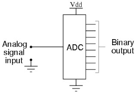

Inbuilt ADC of AVR
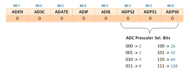
ADC Prescaler
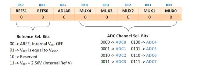
ADC Channels
ADC Channels

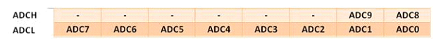
ADC Registers

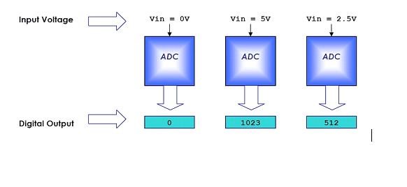
Working with ADC
Programming Steps
/*  Name     : main.c
 *  Purpose  : Source code for ADC interface with ATMEGA16.
 *  Author   : Gemicates
 *  Date     : 2017-09-07
 *  Website  : www.gemicates.org
 *  Revision : None
 */
#include<avr/io.h>
#include<util/delay.h>

void ADC_init(void);
unsigned int ADC_read();

int main(void)
{
	unsigned int value;
	DDRB=0xFF;
	ADC_init();	                                        // Initialization of ADC

	while(1)
	{
		value=ADC_read();
		PORTB=value;
		_delay_ms(500);
	}
}

void ADC_init(void)		                                // Initialization of ADC
{
	ADMUX=(1<<REFS0);	                                // AVcc with external capacitor at AREF
	ADCSRA=(1<<ADEN)|(1<<ADPS2)|(1<<ADPS1)|(1<<ADPS0);	// Enable ADC and set Prescaler division factor as 128
}
unsigned int ADC_read()
{
	ADMUX |=0x00;		                                // selecting channel
 	ADCSRA|=(1<<ADSC);	                                // start conversion
	while(ADCSRA==0x9f);                                    // waiting for ADIF, conversion complete
	ADCSRA|=(1<<ADIF);	                                // clearing of ADIF, it is done by writing 1 to it
 	return (ADC);
}